Owner's Manual Version 2
Table of Contents
Important notes for all installations
Note About The Door Placement
Take great care in handling the door/door structure. If the door swings open on its own all the way, it can break the hinges. The hinge may go on either side, so position it next to the wall. The wall keeps the door from falling open all the way.
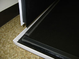
Since the sides normally bow out and it is better for them to not touch the wall, position the tank 2 1/4 inches (5.7cm) from the closed wall.

Warm Salt Before Use
The salt should be as warm as possible before it is put in the tank. So bring it in out of the cold if appropriate. The water that you put in the tank should be as hot as possible. If you are comfortable adjusting the temperature of your hot water heater turn it up at least 1 hour before you plan on filling the tank. And, don't forget to turn back to standard when you are done.
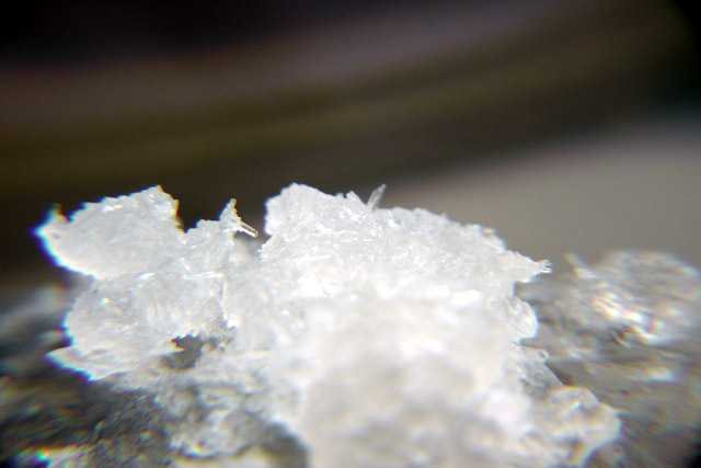
Warning: Sharp Crystals
Please note, when draining or refilling or moving the tank, the solution can dry in a very sharp needle like form. So be obsessive compulsive to make sure not to get any of it between the liner and the tank or wash very thoroughly. Otherwise it can puncture the liner and cause leaks.
Environmental Conditions
The tank is not designed to be installed outside or in bright indirect sunlight. These conditions age the plastic unnecessarily.
Receiving Shipment
Checking Your Shipment
Visit the link below for instructions on checking your shipment.
Instructions for checking your shipment.(READ)
Please read before receiving shipment
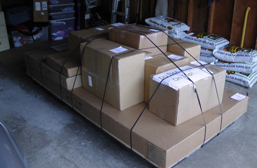
Receiving shipment on pallet
Keep plywood if you have optional sound isolators or optional speakers.
Sound Isolators
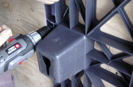
Remove boxes from pallet and pallet from plywood.
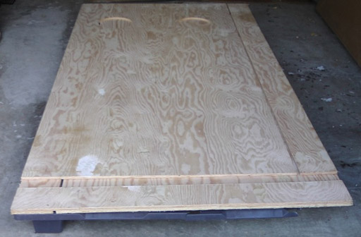
Keep plywood and remove the pallet.
Separate the pieces from each other.
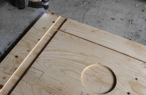
Align the 2 large pieces 1/2" x 41 3/4" x 19 5/8" (2.5 x 106 x 229 cm) and glue and screw them together.
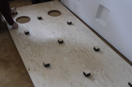
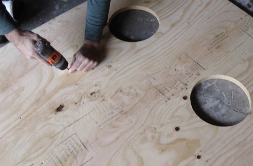
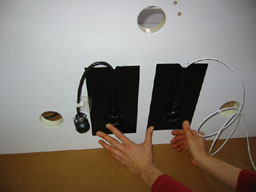
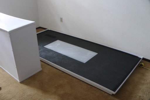
Attach wood squares and sound isolators one above the other (either one first) to plywood. Center row -- 44" and 20" (111 and 51 cm.) from each end. Side rows are 8" (20cm.) from each side and 8" and 32" (20 and 81cm.) from each end. Turn plywood over and place it where tank will be set up.
Transducers (speakers)
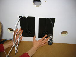
If you have the speakers (transducers) but not the sound isolators then use just the thicker wooden spacers in place of the sound isolators and the wood pieces to lift the plywood high enough that the transducers do not touch the floor. Position the pieces of wood the same as the sound isolators.
Attach transducer (speaker) mounting plate to under side of tank bottom with screw holes provided.
Attach the transducers with hanger bolts (bolt without head) provided.
Body of Tank
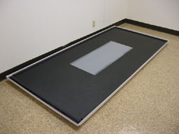
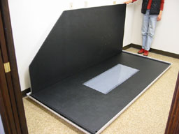
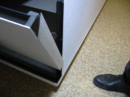
Locate your bottom where you want your tank to be. The underside of the bottom at the rear has an oval recess. The hinge needs to be close to the wall, so that the door, when open, can rest against the wall. The door MUST be supported to protect the hinges.
Left side.
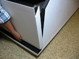
Bottom of side sets down onto rail.
Another view of the left side being set onto the bottom.
Left side in place.
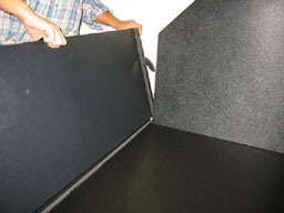
Right side.
Right side in place.
Front.
Front.
Front.
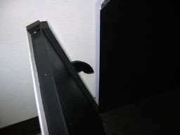
Front hook into side slot.
Front in place. May have to push down with all of your weight, to get it down. Same with the back.
Back.
Heater and Control Sensor
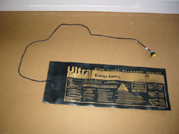
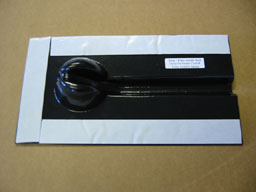
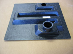
Heater (may be a different model).
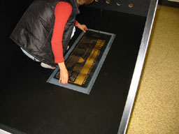
Heater centered over white plastic.
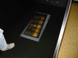
Heater should be even, not like this.
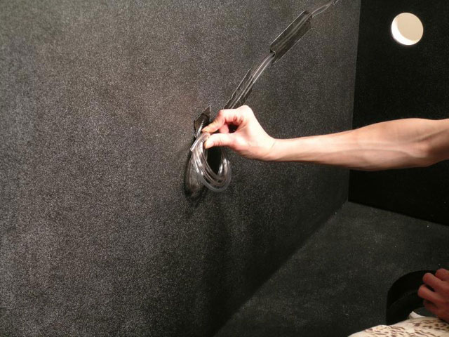
Put heater cord out the middle hole closest to the wall. Bring the bag that the heater is in up the back. Fold the end over and tape it to the back. This will keep condensation from running down the back into the bag.
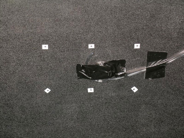
Remove backing from double faced tape.
Attach snugs to outside of back. Put heater cord on side closest wall, sensor away from wall.
Heater cord comes out , sensor wire (in this case, white) goes in.
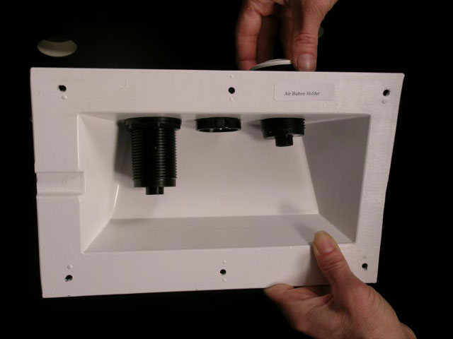
Air Button Holder
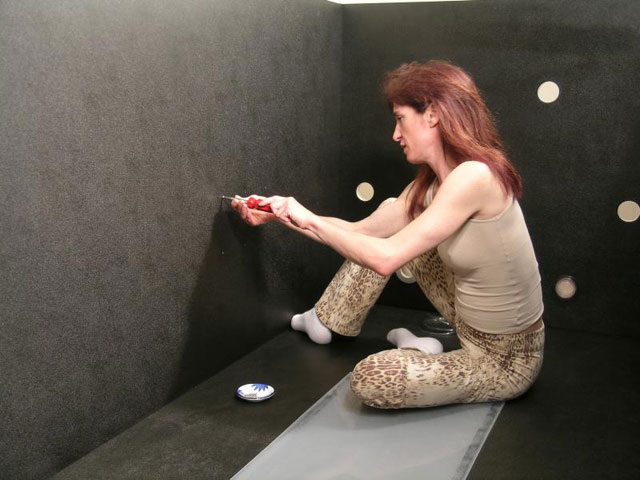
Air switches such as the light and the floater comfort control have an air button holder screwed to the inside of the left wall of the tank.
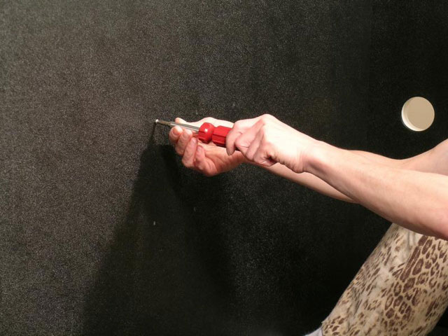
Remove the screws from their holes.
Save screws for later.
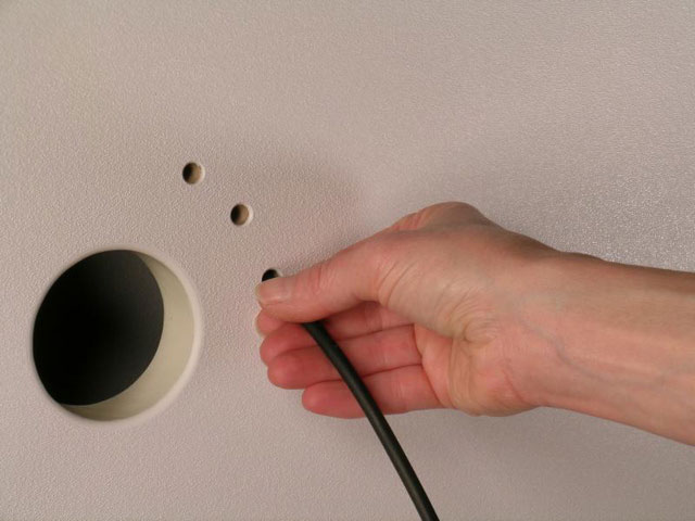
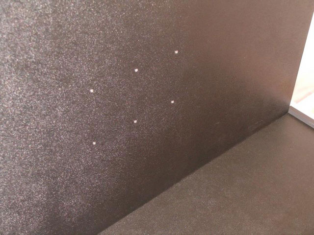
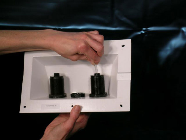
For each air switch, put a rubber tube into little hole in back (since photo, holes have moved to edge of back).
Attach clear tube to rubber tube inside hole. Run clear tube to center of 6 holes and tape in place. Be sure tube is exactly in the center of the right 2 screw holes.
Here tube needs to be slightly higher to be centered between right holes.
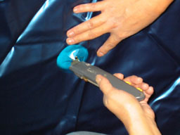
After installing liner, cut a small hole in middle of 6 screw holes.
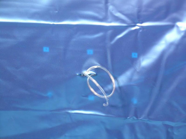
Pull clear tube through hole.
 Install air buttons into holder.
Cut clear tubes about 1' (.3m) beyond liner slit and attach tube to air button.
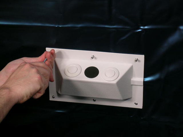
Screw the holder in place locating it against the guides.
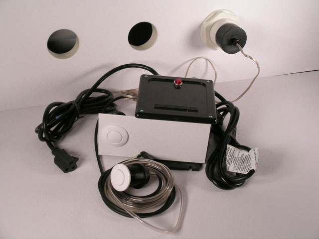
Light
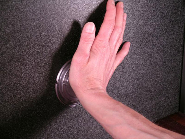
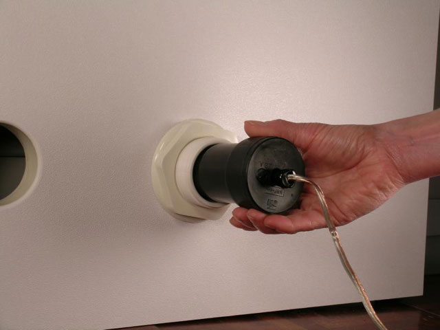
Push the light lens through one of the lower outside holes in back.
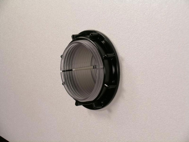
Screw nut on the outside.
Slide light reflector with bulb on the outside.
Light.
Remove protective backing from double faced tape.
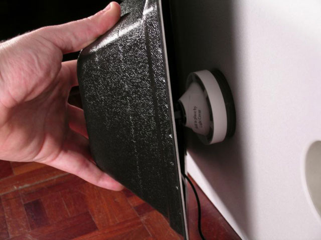
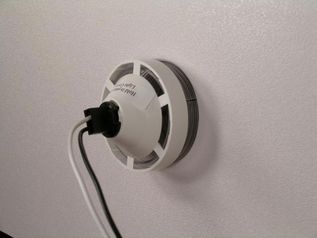
Adhere light cover over light.
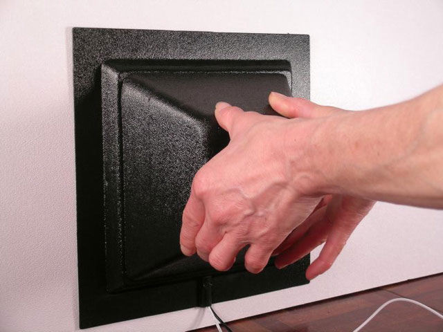
Wire comes out groove.
Floater Comfort Control
Floater comfort control.
Install buzzer of floater comfort control in a thru the wall fitting in one of the outer bottom two holes.
Plug the power cord into the back of the top and into the Floater Comfort Control (FCC) or if you do not have the FCC then into power. If you have the FCC, learn more at Floater Comfort Control.
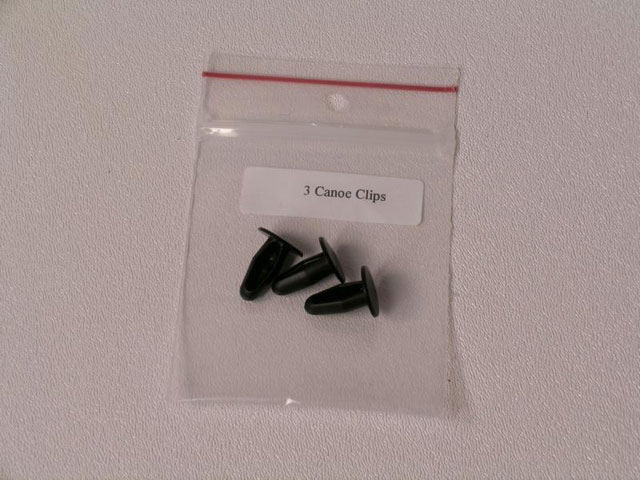
Insert Canoe Clips
The three 1/4" (.6cm) holes in the back, near the left side, need these canoe clips in the holes from the inside, except for the ones that have tubes in them for the optional light or floater comfort control.
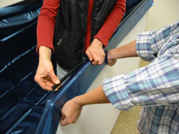
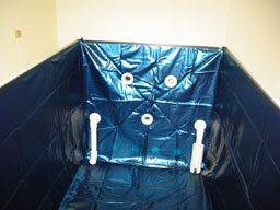
Liner
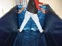
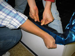
For correct liner fit, put toes in corner.
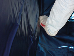
Toe holds liner in corner.
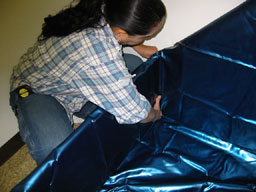
Hold corner in place and pull the liner up.
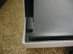
U channel holds liner in place and goes on the inner protrusion.
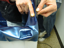
NOT THIS WAY on outer protrusion.
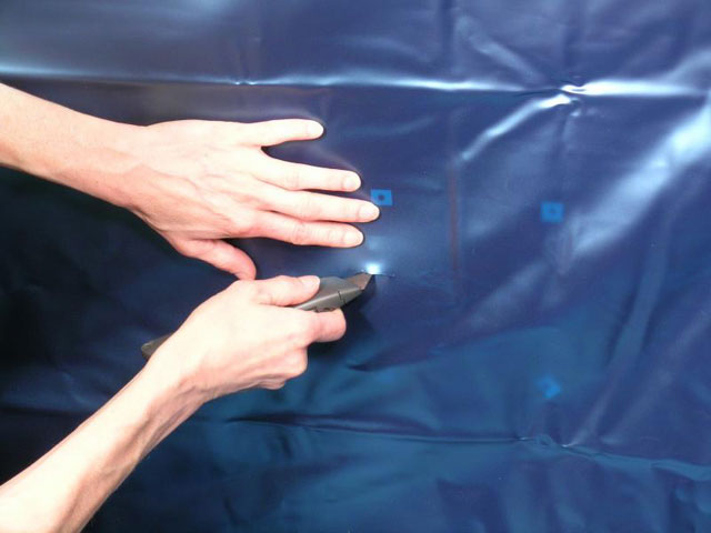
Start at the end, pushing down as you go, until you get to the other end.
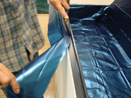
Cut liner just outside inner protrusion.
Filtration Fittings
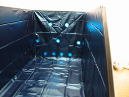
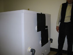
Liner in place. Next cut holes. Bottom 4 holes do NOT have liner cut, because they are below water level (note that the bottom outer holes often have black squares covering them). Cut only the middle and top holes. (Also one top hole isn't cut for two way communication.)
Pie cuts, 1/2" from edge of hole to center.
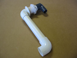
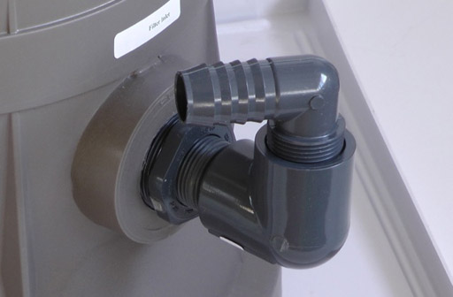
Discharge.
Through left middle hole.
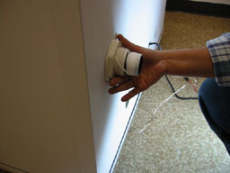
Screw nut on the outside.
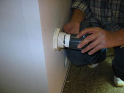
Screw the grey angle on.
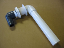
Insert the suction fitting in the right hole and the skimmer around the suction pipe with the notches facing up.
Through the wall fitting (TTWF) for air in (center hole).
Same for the top 2 holes (labeled air out and options). Be sure to screw on their nuts.
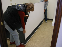
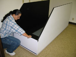
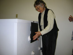
Door and Door Structure
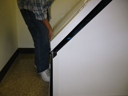
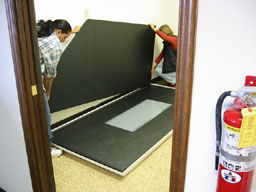
Door structure, hinge near wall. (Take care that the door doesn't accidentally swing open). Set bottom of door structure in place first.
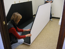
It may not fit down all of the way on the front if the sides are too close to each other. So push the door structure back (at the bottom of it) and then down over the front.
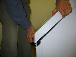
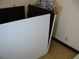
Structure being set in place. Open the door and reach inside and run your fingers between where they connect. If there is any question whether it is seated down on the front, push the sides out from inside and then repeat pushing the structure back and then down until it is in place.
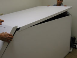
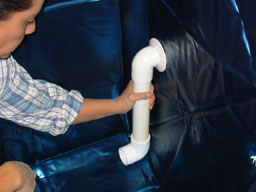
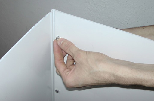
Lift top of door structure so the front of the top will go into place. Door structure down, lift front of top, top forward, and then down in back. If this doesn't work easily, put top down in place including at the back and try the following. Rest your weight on the top of the door structure (like person's left hand is placed) and with the other hand give a sharp upward blow underneath the top at the front.
Putting your hand through the door opening, check inside where the door structure meets the top to insure that they meet well with no gap. If there is a gap, retrace your steps until you are successful. There should be very little black showing at the corners of the structure on the front and top and also on the back below the top. Then with the screws provided in the largest shipping container screw the corners of the structure to the top and front. The holes drilled should line up. Then do the same in the back under the top.
Attach the power cord supplied to the back of the top and plug it into power or into the floater comfort control if you have that option. This prevents condensation.
Since the underside of the top is being heated to prevent condensation, the under side of the top expands, resulting in the middle of it sagging a small amount.
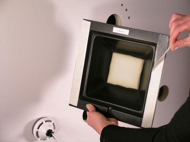
Stills
Still bottom is closest to the viewer.
Installing still in the through the wall fitting (TTWF) labeled air out.
Second still in the center TTWF labeled air in.
Filling the Tank
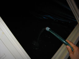
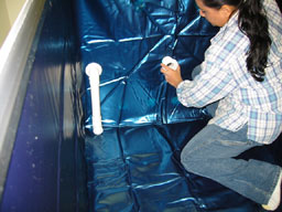
Add 1/2" to 3/4" (1 to 1.5cm) of warm water.
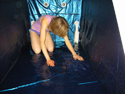
Smooth out the liner.
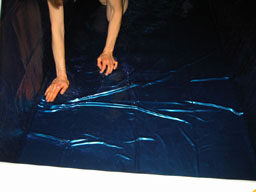
Get all of the wrinkles out.

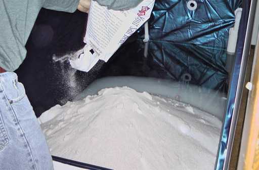
Start adding 700 pounds (320kg) of epsom salt. Add as hot water as you can into the center of the salt pile. Stop for an hour when it starts to not be very hot.
When all of the salt is in and the solution is 10" (25cm) deep, stop the water, get in, and mix the salt. Do NOT leave any salt on the heater or near the suction pipe.
Adjusting the Solution Temperature
Once the tank is filled and salt is off the heater, plug the heater into the digital temperature control.
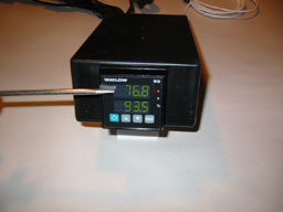
Digital temperature control. The top display shows the solution temperature, assuming the sensor is touching the liner in back.
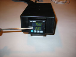
The lower display you set to whatever you want the temperature in the tank to be. 93.5 may not be the correct temperature, but it is a good place to start. Adjust it to your comfort.
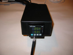
If, when you float, you are too cold, the set temperature needs to be higher, so press the up button. Wait at least half a day, float and adjust it again.
If you are too hot when you float, lower the temperature by pressing the down button. Repeat the whole process until the temperature is exactly comfortable for you.
When the solution is not up to temperature, or the salt is not all dissolved, the solution may stratify and never heat up. What happens is the heavy solution stays on the bottom, gets hot, and the rest stays cold and never heats up. To solve it, mix it frequently. Be sure the salt is away from the heater and away from the suction pipe and then turn on the filtration system at least twice a day. It is fine to just leave it on, though you should run it for a while before leaving it going unattended.
To adjust the temperature:
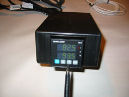
- Get the solution to 93.5(34.2C)
- Float and note weather you are too hot or cold
- Increase the set temperature if too cold
- Or decrease if too hot
- Wait 1/2 day or til the temperature has adjusted
- Repeat floating and adjusting til comfortable
- Note, when well mixed, solution temperature raises .6 degree F (.33C) per hour.
Filtration System
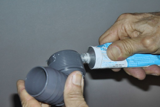
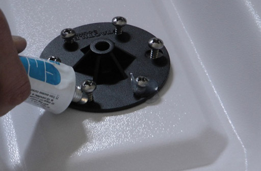
Be sure to put silicone sealant (supplied) in the valleys of all of the threads of the fittings. Even the ones with Teflon tape on them. Be also sure to not move the fittings more than 3 hours after the system is put together otherwise they may leak.
This is slid on too far and is wrong.
When sliding tubing or hose cuffs over barbed fittings, do NOT slide on further than necessary. This is too far.
This is correct.
ALL TUBING AND HOSES NEED TO BE CLAMPED TO THEIR FITTINGS.
Screw an elbow fitting into the filter out. All fittings should be hand tight. If system does not have ozonator, leave fitting facing right. If system does have ozonator, then face up.
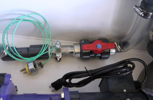
If no ozonator, attach the grounding system. Clamp all tubing ends. Be sure to plug the plug into a grounded outlet or call us at Samadhi Tank Co. 530 477 1319.
Ozonator
If there is an ozonator, attach the manifold to the filter out fitting. Clamp tubing ends.
Ozonator
If there is an ozonator, be sure to plug the grounding wire into a grounded outlet or if none is available, call us at Samadhi Tank Co. 530 477 1319.
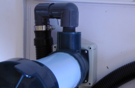
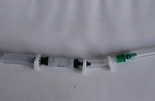
Attach the fittings to the filter inlet. There are four fittings in all.
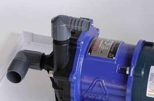
Screw the pump in and out fittings onto the pump.
Attach the tubing onto the pump out fittings and the filter in fittings. Clamp tubing ends.
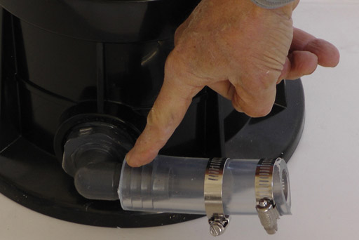
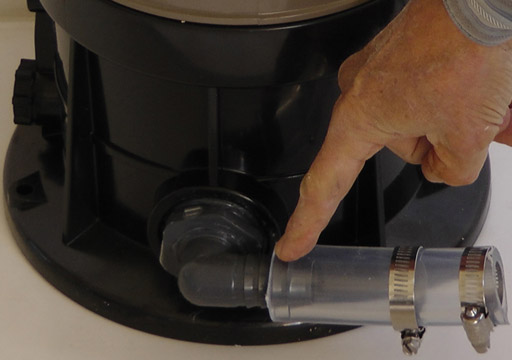
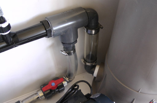
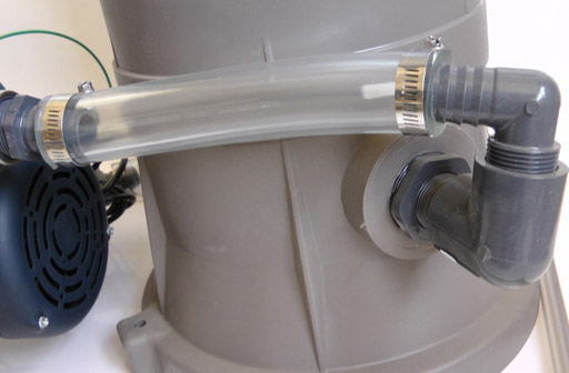
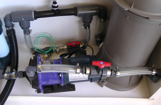
Attach the fittings to the hair catcher and the hose to them. The other end of the hose goes to the discharge fittings on the left side (as you face the tank from the front). Clamp tubing and hose ends.
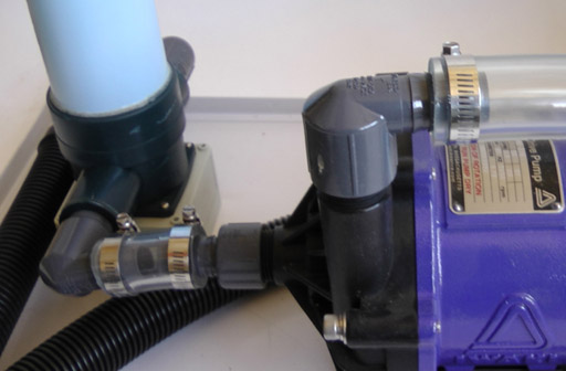
Attach the fittings to the hair catcher out and then connect the hair catcher to the pump inlet with the short tube. Clamp both ends of the tubing.
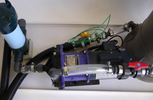
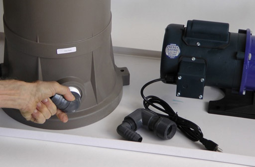
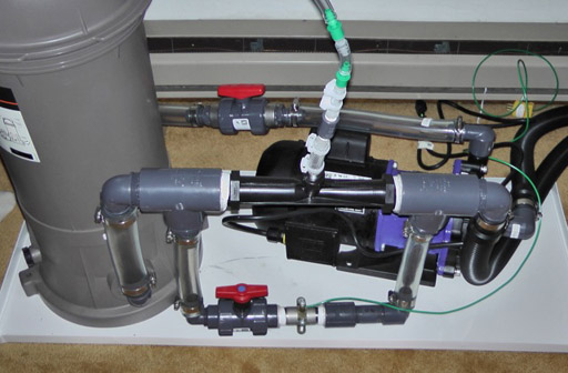
If there is no ozonator, the system looks like this.
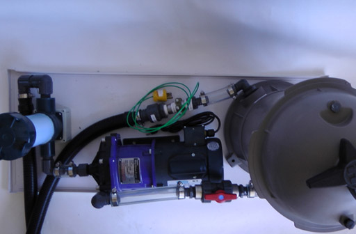
And this.
Bolt the filtration system cover together.
This is together.
Ozonator
If there is an ozonator, there will be tubing to connect to the ozonator and to the manifold. The left end goes to the manifold and gets clamped and the right end goes to the ozonator and does not.
Ozonator
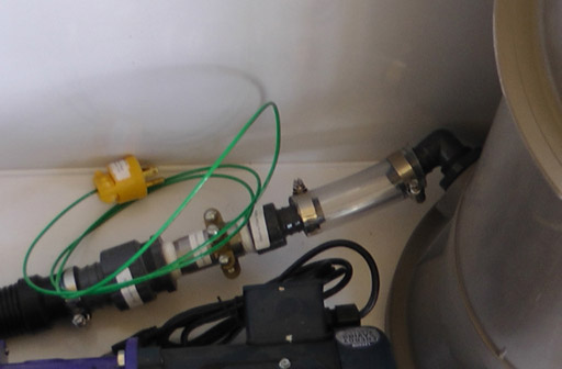
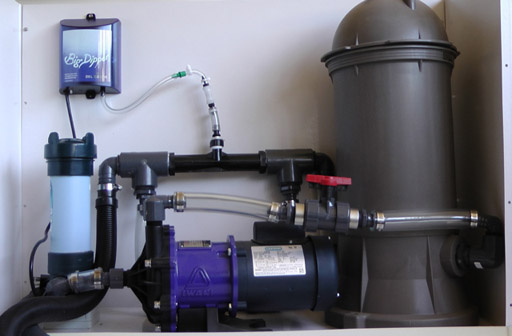
System complete with ozonator.
Ozonator
Another view of the system with the ozonator.
And another. Connect the ozonator to the filtration system cover with the bolt and nut provided. It is best to have the tubing go up from the manifold for a few inches (10cm.).
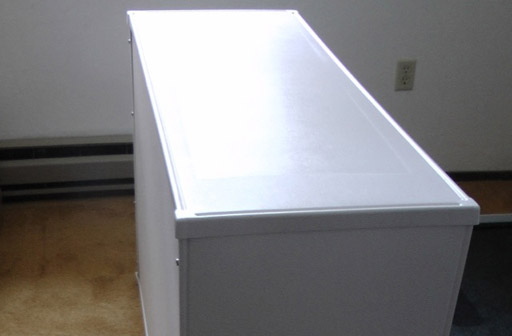
Filtration system cover closed.
Attach hoses -- suction system at back of tank to hair in and clamp hoses to barbed fittings. Clamp other hose to other end of the filtration system either ozonator manifold or grounding system. It will be clamped to the discharge system at the back of the tank, before turning on the pump.
Professional Timing System
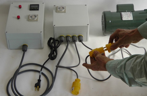
Plug the pump cord plug into the right receptacle of the timer box. If there is an ozonator, plug it into the second from the right receptacle.
The digital timer is set to the time of a float. At the beginning of the float push the red button next to the digital timer. When that timer goes to zero, it initiates the single timer in the smaller box. This initiates the filtration system (letting the floater know their time is up) and the ozonator, which run until the timer goes to zero. The round analog timer below the digital float timer is initiated by the red button beside that timer. That initiates the filtration system for the length of time set on the timer. It can be used to filter for a period of time and then turn itself off.
Prime pump by totally filling the plumping between the pump in and the suction pipe. Do this by either pouring water slowly into the hair catcher until you think this may be done. An alternative is to pour water into the hose going to the discharge system until the plumbing from the suction pipe is filled from the hair catcher to the suction system.
Connect the return hose to the discharge system and clamp both ends. Check that everything is closed up and clamped including the air release valve on the top of the filter top and plug in pump. If after 1 minute the water inside the tank isn't flowing, repeat.